We covered SCCB protocol signaling in previous post, and we will dive into the SCCB structure in this post. Below is the diagram of SCCB, it shows one master device connects to one slave device. Multiple slave devices can be connected to the same bus.
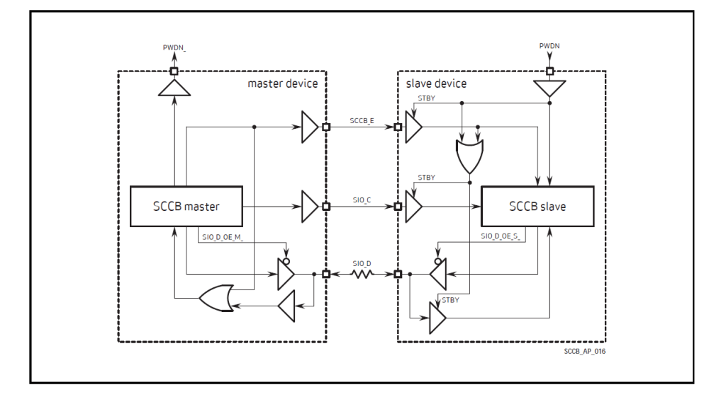
Master Device
Both SCCB_E and SIO_C are driven by the master device, while SIO_D could only be driven by either master or slave devices. The master device must block the SIO_D input to avoid the unknown status propagation during the SCCB_E de-assertion. During the don’t-care bit transmission, the master device has to ignore the SIO_D status and continues to assert in next phases.
Slave Device
Based on the diagram, inputs of slave device: SCCB_E, SIO_C, SIO_D, they all include standby (STBY) control terminal which reduces the leakage current when the input are floating. During the suspend cycles, the output terminals of those inputs pads are driven high when the STBY asserts. This avoids the logical errors.
Comparison with I2C
SCCB is similar to I2C, but they are not the same:
- SCCB is specially designed for camera control modules, while I2C is a general-purpose communication protocol for a wide range of devices
- SCCB usually operates at 100kHz, while fast mode could go beyond 100kHz. I2C, on the contrary, has Standard-mode(100kHz), Fast-mode(400kHz), Fast-mode Plus(1 MHz), and High-speed mode(3.4Mhz)
- SCCB can only write or read one byte of data per transmission, but I2C can write or read multiple bytes in one transmission

Leave a comment