
Histogram can be implemented in hardware for collecting distributions of run-time data cycle by cycle. The results are later read by software for further analysis, and we assume that software read can only happen after hardware is fully quiesced.
The problem consists of 2 parts: figuring out which interval the data belongs to, and updating the histogram data structure. The former can be treated as a search problem, and we only focus on the latter here.
Assuming there are M intervals, and each interval needs to hold a value up to (2N-1). Logically speaking, the histogram data structure is an (NxM)-bit array.
The General Solution
The most straightforward way is to use flop arrays to implement the histogram data structure. All intervals can be cleared in a single cycle before any data processing starts, such that histogram data structure can always start with a clean initial state.
If the histogram needs to handle up to L distinct data inputs per cycle with no backpressure, the histogram update operation can be implemented with:
- M adders, with each adder incrementing by at most L per cycle
- L adders, with each adder incrementing by 1 per cycle. Additionally, each adder requires 1 M-to-1 mux and M 2-to-1 demuxers. The first data input selects one out of M intervals and increments that interval by 1; The second data input selects one out of M results of the first data input, etc.
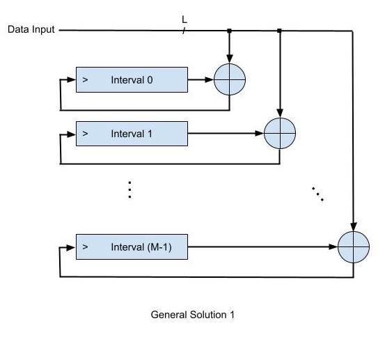
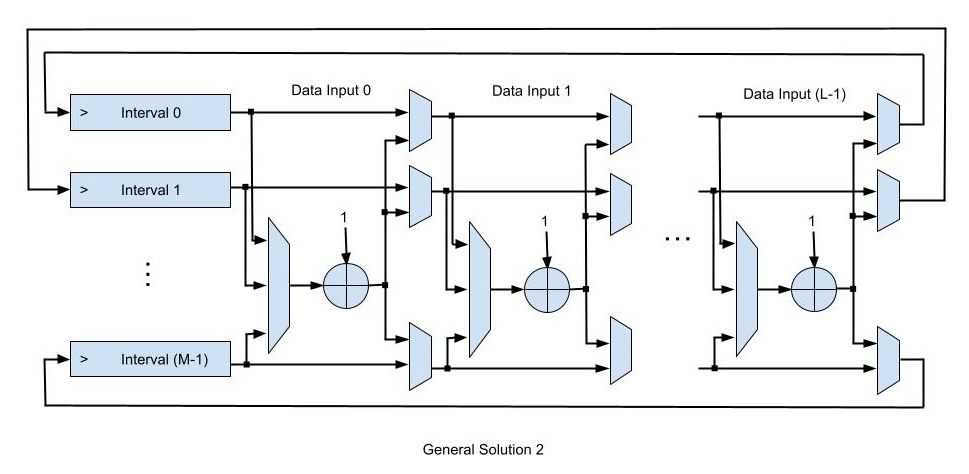
The designer needs to evaluate which option above is more area efficient, before implementing it in RTL. The trade-off comes from the correlation across M, N and L.
Optimizations if (NxM) is large and L is 1
If (NxM) is large and L is 1, using flop arrays could be quite expensive in area. We should switch to an SRAM with 1 read port and 1 write port for the histogram data structure, and one SRAM entry maps to one histogram interval.
Before any data processing starts, the SRAM clear operation can no longer be completed in a single cycle. Software will have to reset the SRAM entry by entry across M cycles. Alternatively, we could implement an M-bit array, indicating whether the corresponding SRAM entry holds valid value. This M-bit array gets cleared in a single cycle before any data processing starts. The later discussion will assume the alternative approach.
The main challenge of using SRAM is, if the SRAM entry holds valid data, updating that SRAM entry requires a read-modify-write (RMW):
- Cycle 0 / Stage 0: SRAM read enable can only be asserted
- Cycle 1 / Stage 1: SRAM read data is available
- Cycle 2 / Stage 2: SRAM read data is flopped for timing. SRAM write enable can only be asserted in this cycle as well
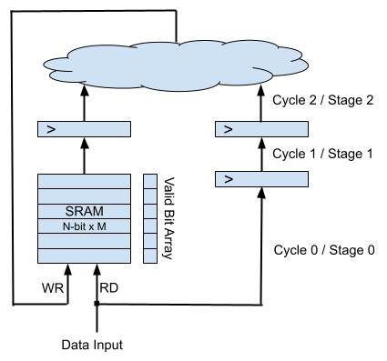
One RMW operation requires 2 cycles to complete, during which 2 new data inputs may appear and should be accounted for in the histogram. Obviously, we need to carefully take care of data hazards and data forwarding in flight. In Cycle 0 / Stage 0, when a new data input appears:
- If the corresponding bit of the M-bit array is 0, the SRAM entry does not hold valid data, nor does there exist outstanding RMW in Stage 1 or 2. In this case, hardware simply sets that bit to 1, and the SRAM entry would eventually be updated to 1 in Cycle 2 / Stage 2
- If the corresponding bit of the M-bit array is 1, depending on whether there is outstanding RMW in Stage 1 or 2, hardware takes different actions:
- If there is no outstanding RMW in Stage 1 or 2, the corresponding SRAM entry must hold valid data. Hardware asserts SRAM read enable and reads the SRAM entry. The SRAM entry would eventually be incremented by 1 in Cycle 2 / Stage 2
- If there is outstanding RMW in Stage 1, hardware skips SRAM read in Stage 0, and “informs” Stage 1 that, instead of incrementing by 1, it shall increment by 2
- If there is outstanding RMW in Stage 2, hardware skips SRAM read in Stage 0, and “informs” Stage 2 that, instead of incrementing by X, it shall increment by (X+1), where X = 1 or 2
- There shall never be outstanding RMW to the same SRAM entry in both Stage 1 and Stage 2. One should write an SVA to detect this illegal case
Does SRAM Solution Always Work if L > 1?
The short answer is NO. If L > 1, a single piece of SRAM is not able to sustain throughput requirement: one SRAM can only sustain one read per cycle, but multiple data inputs demand accessing multiple SRAM entries per cycle.
In this case, we will need L banks of SRAMs, with each bank tracking one data input. When software reads the histogram, hardware needs to accumulate the read data from multiple banks.
If L is large, SRAM based solution may not necessarily bring area benefits compared to the general solution. Again, the designer shall properly evaluate the trade-off by evaluating the correlation across M, N and L.


Leave a Reply