In our book “Crack the Hardware Interview – Physical Design & Silicon Debug”, we discussed that noise fix is an essential step during timing ECOs. We will dive a little deeper into this topic.

What is Noise / Crosstalk?
Noise / crosstalk analysis is a type of signal integrity analysis completed during physical design. When two or more nets are physically close to each other, they suffer from mutual signal interference due to capacitance coupling.
Consequently, noise / crosstalk can incur delay increasing or even logic errors.
Crosstalk Increases Delay
As shown in the diagram below, when signal B is toggling, if signals A and C are also toggling and their capacitance coupling with signal B is strong enough, signal B may need more time to toggle.
In the above crosstalk analysis, we assume signal B is the “victim”, and signals A and C are the “aggressor”. In fact, A and C can also be the “victim”, and B can also be the “aggressor”.

It is obvious that, when B is toggling from 1 to 0, A’s toggling from 0 to 1 may slow down B, while C’s toggling from 1 to 0 can speed up B. If A’s influence on B is strong enough, the overall timing closure might be an issue.
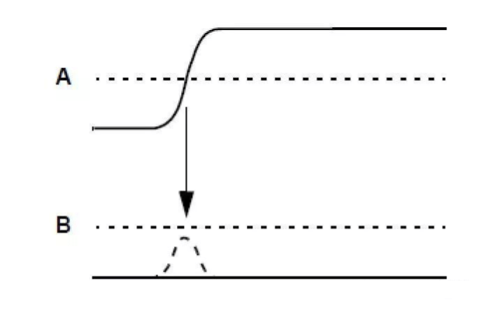
Crosstalk Incurs Logic Errors
Crosstalk could incur glitches, or even logic errors. As shown in the diagram below, signal B has no toggling, but signal A is toggling from 0 to 1. Signal A’s behavior incurs a small glitch on signal B. When this glitch is high enough and lasts for a long period of time, the downstream logic of B will capture a 1, instead of 0.
Such glitch violation is unacceptable in STA, and it is a must-fix.
Dealing with Crosstalk in Physical Design
There are several techniques to address crosstalk in physical design, including:
- Downsize aggressor net’s driving cell
- Upsize victim net’s driving cell
- Increase the distance between aggressor and victim
- Add “shielding” between aggressor and victim
- Add buffers to victim nets
Oftentimes, noises are modeled as uncertainty, and designers are fixing crosstalk by adding margins to the timing paths. However, blindly adding margins during timing fixes introduces unnecessary waste of area and power.
Instead, designers should try identifying timing critical paths, possibly adding shielding to those paths, and inserting “guide buffers” to direct the placement and routing away from areas with dense aggressors.

Leave a comment