After an overview of the SCCB protocol, we will dive into SCCB signaling in details. Below is the Pin description from the specification:
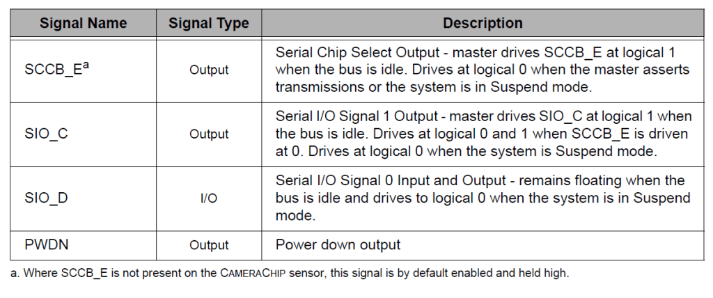

- SCCB_E
SCCB_E is an active-low, one-directional signal controlled by the master device. During data transmission, SCCB_E must be set to 0; When bus is idle, the SCCB_E must be set to 1. - SIO_C
SIO_C is an active-high, one-directional signal, also controlled by the master device. SIO_C represents each data transmitted bit. When the bus is idle, it is driven to 1; otherwise, a data transmission starts when SIO_C is driven to 0 and then back to 1. - SIO_D
SIO_D is a bi-directional signal. Since SIO_C going from 0 to 1 indicates a single transmitted data bit, the SIO_D can send the data only when SIO_C is 0. When the bus is idle, SIO_D is floating or in tri-state.
Below waveform would help you to have a better understanding of the signal behavior during SCCB protocol data transmission.


Leave a comment